Typical Example Of A Load Bank For PSU Testing:
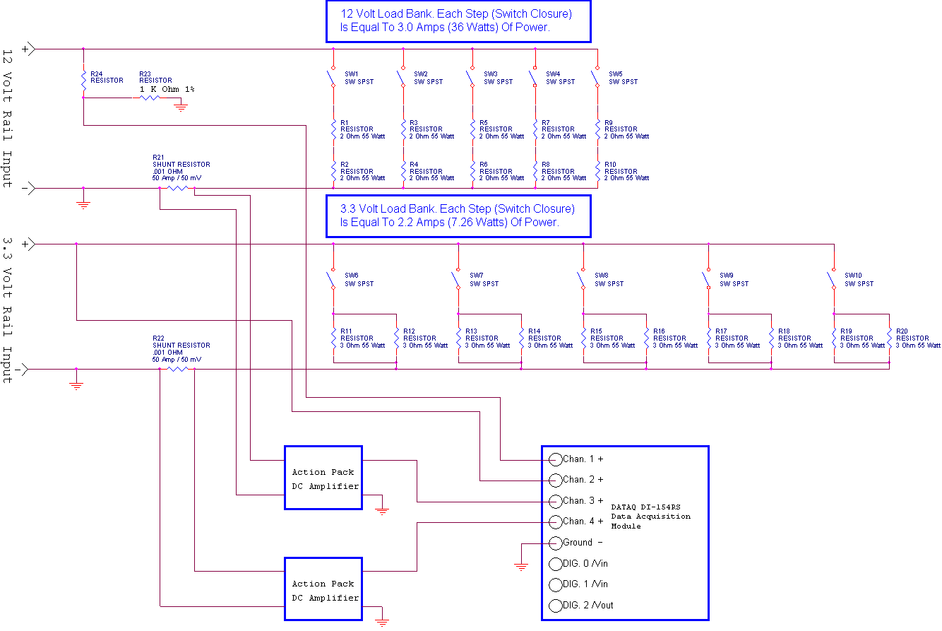
The above schematic represents a prototypical design concept for a device to test ATX & BTX Form Factor Power Supply Units as used in most personal computers. The unit as drawn will look at a single 12 Volt rail and a single 3.3 Volt rail from the PSU and apply loads simulating a computer drawing power. Resistors R1 through R10 provide the loads for the 12 Volt bank. Resistors R1 through R10 are all 2 Ohm Wire Wound Power Resistors rated at 55 Watts of power dissipation. This design concept was built / drawn around existing parts. Looking at the first two resistors in the 12 Volt bank, R1 and R2. These resistors are placed in series, R1 + R2 in series = 4 Ohms. When SW1 (Switch #1) is closed this will place a 4Ω load across the incoming 12 Volt rail. The basic math of Ohms Law tells us that the Current (I) is equal to the Voltage (E) divided by the Resistance (R). Therefore I = E / R. The current in the above circuit when SW1 is closed would be 12 / 4 = 3 Amps. Power as expressed in Watts is equal to the Voltage times the Current or P = E * I. Closing SW1 would produce 12 * 3 = 36 Watts.
Now a little bit about the above circuit. Had I used single 2Ω resistors the current would have increased to 6 Amps and the power would have been 72 Watts. This would have well exceeded the power rating of the resistors. It should be noted at this point looking at our numbers that resistance and current are inversely proportional. Hold that thought because when resistors become hot their resistance begins to increase rapidly. Typically, we want to use resistors well within their rated power limits. We also like to employ the use of fans to remove the heat buildup on resistors when used in load bank applications. I have omitted the fans from the drawing however they would be used. Their placement and airflow would be a function of the physical construction of the power resistors used in the design. Power resistors come in a variety of flavors.
Moving along, closing switches SW2 through SW5 will successively add load to the PSU under test on the 12 Volt rail. The total current will increase in 3 Amp steps adding 36 Watts of load per step. When SW1 through SW5 are all closed the total current load will be about 15 Amps or (15 * 12) = 180 Watts. Therefore we can increment our load up in 36 Watt (3 AMP) steps to a total power of 180 Watts.
Looking at our 3.3 Volt rail, things are done in much the same manner. However our resistors R11 through R20 are configured slightly different. This time I have placed 3Ω resistors in a parallel rather than series configuration. Unlike a series configuration where we add the values of the resistors to get a total resistance, to calculate Rt (Resistance total) we apply the following formula. Rt = 1 / (1/R1)+(1/R2)+(1/R3)+... so in our case we have 1 / (1/3)+(1/3) or 1 / .333+.333 or 1 / .666 = 1.5 Ohms. Therefore each switch closure from SW6 through SW10 places 1.5Ω across the 3.3 Volt rail drawing 2.2 Amps. Therefore 2.2 * 3.3 = 7.26 Watts. Since we have 5 banks closing SW6 through SW10 would produce a load of 36.3 Watts. It should be pointed out that in an actual load bank the resistors of choice would likely be 1Ω pairs in parallel yielding 0.5Ω. This load would draw 6.6 Amps and result in a 21.78 Watt load per step. Using 10 steps a 3.3 Volt rail could be loaded to 66 Amps and 217.8 Watts.
So how do we measure all this stuff? Since the current is the more difficult lets begin there. You will see two resistors labeled R21 and R22 in the above schematic. Though I designated them as, and drew them as Resistors they are devices called Current Shunts. A Current Shunt is in a sense a resistor. When current flows through a resistor it produces a voltage drop across that resistor. The current shunts I have used have a very, very low resistance. The actual resistance is a precision .001Ω. Therefore if we again apply some Ohms Law we can derive the voltage drop across the shunt based on the current flowing through it. Pretty cool huh? Lets say in the above circuit we close SW1. We should have a current draw of 3 Amps. Based on a derivative of Ohms Law E = I * R therefore 3 * .001 = .003 Volts or 3 mV. Using a .001 Ohm shunt works well because it produces 1 mV / Amp output.
Now I got a little sneaky at this point. I have done a few things in this prototype I would not do in a full blown working version. I had to do them for good reasons I will explain shortly. I am using an A/D (Analog To Digital) converter to measure my data. There is more about this particular device below in: Typical Example Of A Cool Device For PSU Testing. This is a very simple basic device. My choice would be to employ a much better device in an actual unit. The device I have shown has four input channels. Each channel has a fixed input range of + / - 10 Volts. Since the shunts output .001 Volt / Amp I needed to amplify the low DC level. I incorporated a few "Action Pak" units as DC amplifiers. These convert the outputs of the shunts to 0 to 5 Volts. Thus a range from the shunt of 0 to .050 Volt now becomes 0 to 5 Volts. This affords great resolution for the current measurement process. Additionally they provide isolation for the shunt outputs. That is important for a number of reasons. Remember, even the "common" sides of the shunt outputs are not at true ground potential, close but not at true ground potential.
I employed another little trickery (OK, no trickery but basic electronic theory). As I mentioned the data acquisition unit only has a single channel range of + / - 10 Volts. So how do we measure the 12 Volts when it exceeds the range of the measuring device? Looking at where the signal is "picked off" for the 12 Volt rail measurement you will see a few more resistors. These are R23 and R24 they are both 1KΩ (1,000 Ohm) resistors and I just noticed I forgot to designate R24. Rest assured it is the same as R23. These two resistors serve as what is called a "Voltage Divider" and since they are equal will divide any incoming voltage by two. Therefore now 12 Volts becomes 6 volts at the input to our ADC (Analog To Digital) converter. Having the unit read correctly is easily done employing a curve. That is not important, however examples of doing this may be seen below in Typical Example Of A Cool Device For PSU Testing.
The question begs to be asked "So why use an ADC"? There are several key reasons for using this approach. Lets look at a few of them:
We want to measure several signals here. We want to measure them simultaneously and with accuracy. It would be nice to see all of them at once. The alternative would be the use of one to several DMMs (Digital Multi Meters) employing a switching matrix. Each value would have to be viewed and manually recorded. The switching matrix alone would be a nightmare depending on the number of points we want to measure.
Actual Power in Watts would need to be manually calculated, the alternative to that would be to incorporate a Watt Transducer at an extremely high (forget it) cost. Actual power in Watts for each rail could easily be calculated using a simple software routine using an ADC. Then each rails power could be added and displayed in real time as total power.
A nice looking "Test Report" could easily be generated with the simple click of a button on a form. In fact, during test, the individual performing the test could click a form button during test (following a test procedure) and each step in the test process recorded. The form could allow for entry of Manufacturer, Model No., Tester's Name, Date, and whatever is wanted. The data could easily be compiled and easily presented (printed). The alternative is to compile all this manually.
Efficiency! The AC Line Current could easily be measured on the line side of the PSU and the upstream Watts calculated. The total load watts could easily be compared to the power being drawn on the line side and the Efficiency calculated within the software.
A single ADC can serve the purpose of many DMMs leaving room for future expansion.
The list of reasons why ADC is a good and viable way to go goes on. I plan to build a prototype device using this device to demonstrate its capabilities or more the capabilities of using a system like this for PSU testing in a test bench environment. The actual device I would suggest for a good working bench version for production purposes would likely be a DI-710 Version made by the same company as the small starter kit I am using is made by. http://www.dataq.com/products/hardware/di710.htm carrying a cost of about $500.00.
Wire? I forgot to mention the best choices for wire. The individual loads should be AWG 14. The main lines should be AWG 10. We don't want (I * R) losses as a result of light wire gage. The light instrumentation wiring should be AWG 20 twisted pair leads. We want to keep the wire used in the actual main current paths we are measuring more than capable of handling the current, especially on the 12 Volt rails where a small change in resistance will effect out measurement plane.
A full unit would measure likely two 12 Volt rails (12V1 and 12V2) as well as the 5 Volt, 5 Volt SB (Standby) and3.3 Volt rails. Looking at today's PSUs, there is little to no need to measure the negative rails (-12 and -5 Volt).
Hopefully soon I will have several pictures of the components posted to this page. Kodak moments!
Till Again
Ron
Please feel free to email me with questions here.
Typical Example Of A Cool Device For PSU Testing:
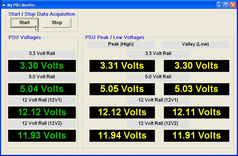
According to specifications ATX, BTX and other Form Factor computer power supplies are expected to deliver voltages within a certain tolerance:
| Output | Range | Min. | Nom. | Max. | Unit |
| +12.0 V1 DC | +/- 5% | 11.4 V DC | 12.0 V DC | 12.6 V DC | Volts DC |
| +12.0 V2 DC | +/- 5% | 11.4 V DC | 12.0 V DC | 12.6 V DC | Volts DC |
| + 5.0 V DC | +/- 5% | 4.75 V DC | 5.00 V DC | 5.25 V DC | Volts DC |
| +3.3 V DC | +/- 5% | 3.14 V DC | 3.30 V DC | 3.47 V DC | Volts DC |
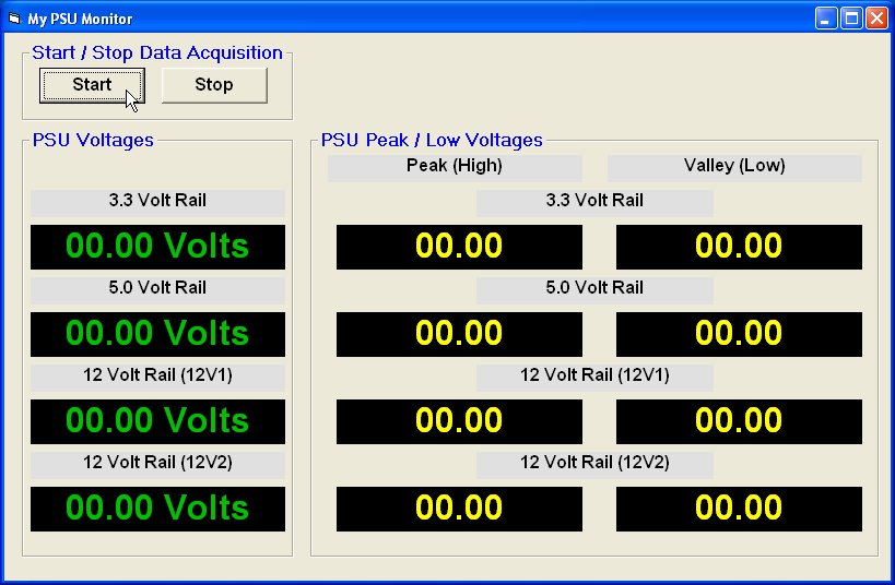
The following is an example of a PSU test panel that can be built for under $50.00. It provides a constant updated view of the main PSU voltages delivered to a motherboard. This example used Microsoft Visual; basic 6.0 to create the panel and a small Analog to Digital (A/D) acquisition device to obtain the data. I should point out that little to no programming skills are required to create one of these. The unit provides the user with a good picture of what the PSU is doing as to voltage outputs.
Prior to starting the test panel:
Test panel up and running the PSU of the machine I am currently using:
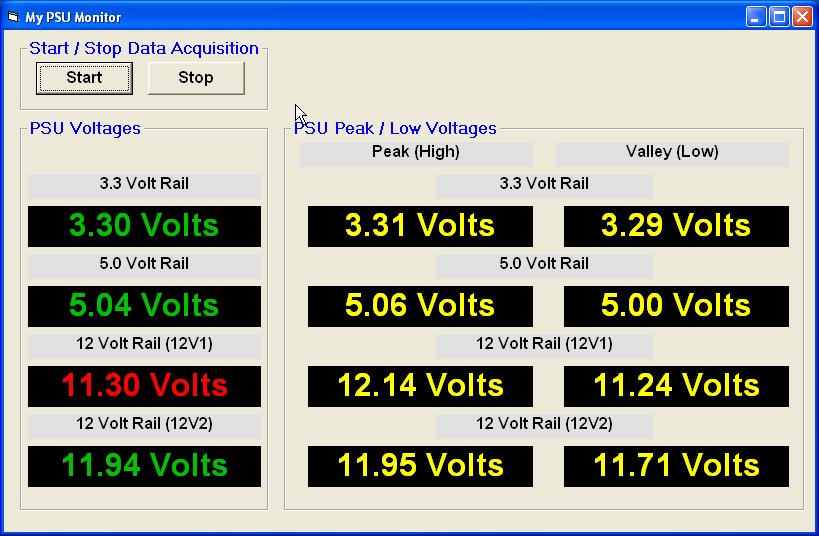
An example of the 12V1 dropping below accepted levels. Note the text changes to RED
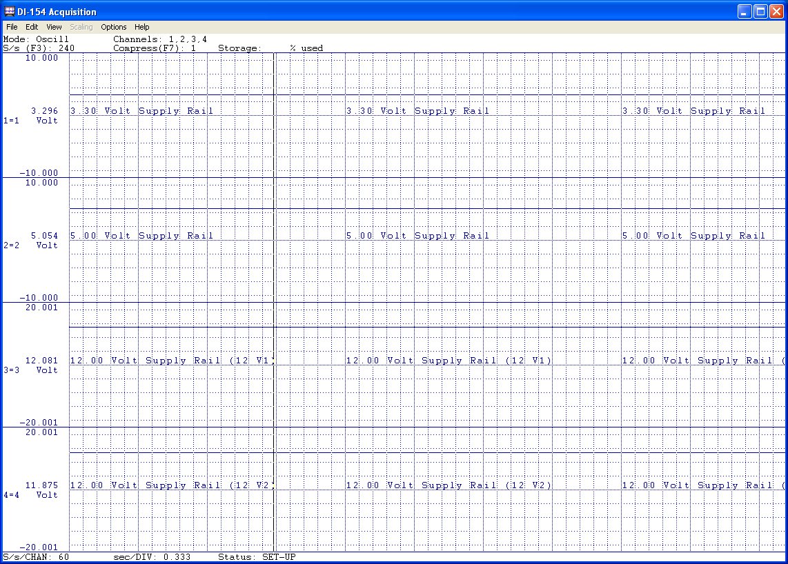
Data acquisition was accomplished using a Data Instruments unit as a Starter Kit. The unit used was a model DI-154RS which has a retail of about $39.00. The DI-154 is a nice little 12 bit unit having 4 analog input channels. These units include some very good charting and recording software, however, I chose to create my own form in VB 6.0. The range is limited to + / - 10 Volts on each channel. To get the 12 Volt readings I built a simple voltage divider consisting of a few 1 KΩ resistors and used the code I wrote to do the math. This sounds more complicated than it is. The downside of this starter kit is the serial RS232 interface. However, if you have a machine with a RS 232 interface you are good to go. The more costly USB kits are much faster and carry a larger price tag. THINK CHEAP!
Dataq even provides code samples for the "home brew" creative types. Though this was done in VB 6.0 I am pretty confident the same could be done in Microsoft's Visual Basic 2005 Express edition which is free and can be had here! I have not used it but it should work for a project this simple. I hope to give it a try for applications like this soon. Additionally I hope to get more posted on these devices soon.
Dataq also includes some nice basic software with their starter kits. Additionally the units can be set to record over a period of time. The below image is a good example of the recording software presenting a screen similar to a paperless chart recorder. The possibilities are endless.
Old Page and Not Current.
Ron