Overall Troubleshooting a computer that does nothing when the power button is pressed.
This guide is written to help the home computer enthusiast whose computer will not start when the front panel power button is pressed. The guide assumes nothing at all happens and the system does not start, the fans don't spin up, there is no post or BIOS activity and nothing at all happens. This guide assumes the enthusiast has no specialized tools such as a DMM (Digital Multi Meter) to troubleshoot the system.
First with the system unplugged from the AC mains power and the rear PSU switch (if applicable) in the OFF position remove the case side panel as applicable to view the inside of the system. Once the side panel is safely removed connect the system to mains AC power and turn the rear PSU power switch to the ON position. Additionally make sure all connectors to and from the motherboard are tight and secure, these include the 20 or 24 pin main power connector and auxiliary CPU power connectors.
NOTE: Make sure the AC mains power is an active working power source. If using any form of switched power strip make sure it is on. Make sure no household circuit breakers are tripped or fuses blown.
With power ON visually inspect the interior motherboard surface for a glowing LED. Most of today's newer motherboards include a power LED which should be ON anytime power is connected to the system and the rear PSU power switch is on. We suggest you check your motherboard manufacturer's manual for the presence of this LED as it can be a very important and useful troubleshooting aid.
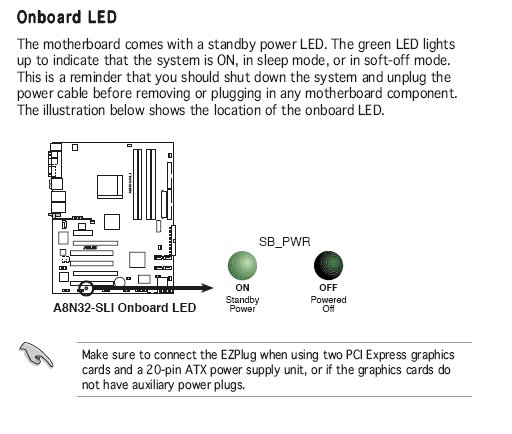
The above image is taken from an Asus motherboard manual. The LED should glow brightly anytime power is applied at the rear of the unit and the rear PSU power switch is in the ON position. This LED when illuminated indicates the presence of 5 Volt SB (Stand By) power to the motherboard. This 5 Volt SB power is essential for the power supply to perform a normal start when the front panel power button is pressed. Should your motherboard have one of these useful tools and the LED is not illuminated with the afore mentioned conditions met of known good power applied and the rear PSU switch in the ON position there is a strong possibility your PSU has failed and should be replaced with a known good PSU capable of the necessary power to run your system.
The next logical steps will be some fault isolation. Assuming the 5 Volt SB led is glowing check the motherboard connection where the case connects with the motherboard. This is generally a pin header as can be seen in the below image.
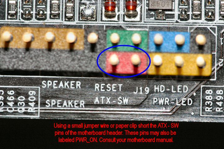
NOTE: Consult your motherboard manual for the location and pin out of these pins. Different manufacturers place the header in different locations as well as use slightly different identification convections. Common terms are PWR-ON, ATX-SW (as above) and others. Consult the manual and don't try to guess. If your manual is lost they can frequently be downloaded from the manufacturer's website.
Remove the front panel leads connected to the illustrated pins for Power On and jumper (short) the pins together. The case front panel power button is a momentary normally open switch, when we press the button it shorts the pins it is connected to. This step eliminates the possibility of a faulty power button or wires from the power button to the motherboard. Does the system start when the pins are shorted? If when the pins are shorted the system starts the problem is likely a front panel power button or the wires from the power button are damaged. Remove and replace the power button and associated wires. Most case manufacturers will replace these parts free of charge. Contact your case manufacturer. Should shorting the pins produce no results, replace the removed wires and let's continue.
The following steps require a little manual dexterity depending on placement of the motherboard main power connector. When the pins we mentioned are shorted by a momentary closure of the front panel power button the motherboard uses the always present 5 Volt SB power we mentioned to send a signal to the PSU through the main PSU / Motherboard connector. This is accomplished through pin 14 of the older 20 pin connectors and pin 16 of the newer 24 pin connectors. This pin is commonly known as the PS_ON pin and is a Green wire. It should be the only Green wire in the connector. We are going to jumper (short) this Green wire to any Black wire on the connector.
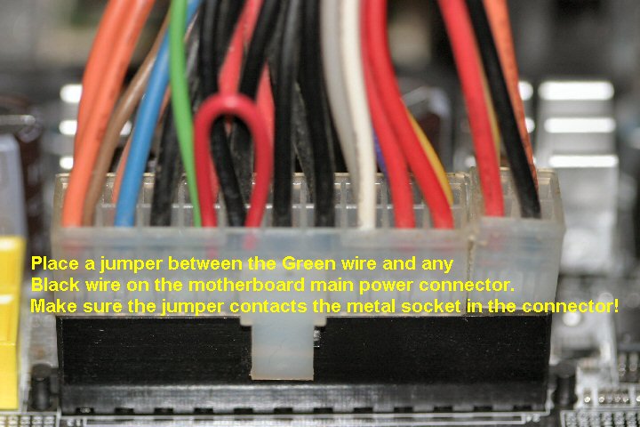
This is done with the PSU connected to the Motherboard. Carefully slip the jumper (wire or a paper clip bent to shape) down beside each of the Green and Black wires. The jumper must be inserted deep enough to make contact with the metal pin sockets in the connector. This test simulates a Logic Low being applied to the PSU on the PS_ON line and is what the motherboard logic circuits would be doing. This is a momentary test! Does the PSU power up? Do the system fans begin to spin? Remember this is a momentary jumper affair, do not leave the jumper in for any length of time. If the system came to life the problem is likely a faulty motherboard, something is precluding a power start command from reaching the PSU.
Another test and a final step we can try is disconnecting the motherboard main power connector and if present the 4 or 8 pin CPU power connector. Leave the optical drive power connected as well as the hard drive connector. Again, with no power connected to the motherboard apply the short between the Green and any Black wire in the connector. Does the PSU start? Do the optical drives show activity? Does the PSU fan start? Again if the answer is a resounding YES the likely problem is the motherboard. However, if again there is no activity then the likely problem is a failed PSU.
These are the first logical steps in troubleshooting a system that simply does nothing when the front panel power button is pressed. Though not foolproof they should afford the home computer enthusiast a basic idea of fault isolation.
Sunday 06 January 2008
Ron